
How to Change a Key-Fob Battery Without Damaging the Remote
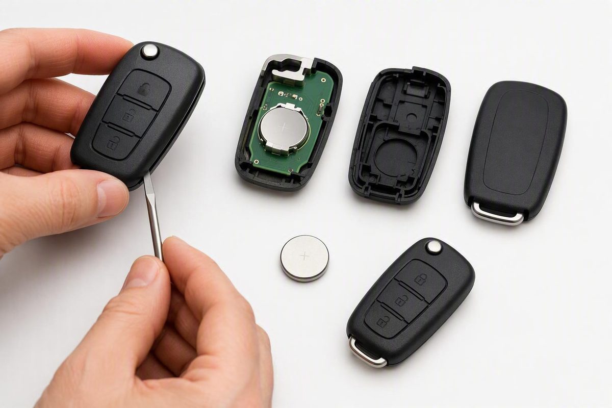
Verify the exact cell, preserve polarity, open the intended access point gently, reassemble without force, and test every applicable function.
Remote keyless entry battery replacement is usually manageable at home, but the details are not universal.
The safest model-agnostic process is to confirm that a weak battery is plausible, identify the exact cell, photograph the original assembly, open the intended access point gently, preserve polarity, reassemble without force, and test every applicable function. If the remote remains unreliable, complete the basic checks before assuming it needs replacement or programming.
Confirm That the Battery Is the Likely Problem
Common signs of a weakening key-fob battery include:
- Reduced operating range
- Delayed response after pressing a button
- A need to press buttons repeatedly
- Intermittent locking or unlocking
- A low-key-battery or “key not detected” dashboard message
- Failed or inconsistent proximity entry
- Trouble getting a push-button-start system to recognize the key
These symptoms suggest a weak battery, but they do not prove that the battery is the only problem. Reduced range, unlocking delays, dashboard warnings, and push-button-start detection trouble are commonly associated with a low fob battery, but incorrect installation or internal damage may produce similar results (AutoZone’s key-fob battery guide).
Consider whether the problem affects every function:
- If lock, unlock, trunk release, proximity detection, and starting recognition all become intermittent, a weak power source is a reasonable suspect.
- If one button consistently fails while every other function works normally, the fault may involve that button, its membrane, or an internal contact.
- Neither pattern is conclusive; use it only as a diagnostic clue.
Inspect the outside of the remote as well. A cracked shell, missing case material, or a button stuck below the surface makes physical damage more plausible.
If you have a spare remote, compare its behavior:
- If the spare works normally, focus your initial checks on the original remote.
- If both remotes behave similarly, interference or a vehicle-side problem becomes more plausible.
- If the spare has been stored for a long time, remember that its battery may also need attention.
This comparison provides context but does not isolate the fault by itself.
A completely unresponsive fob may still have only a depleted battery. Before buying an entire replacement remote, identify the installed cell and check whether it is correctly seated. Battery replacement may restore operation, but it cannot repair worn buttons, a broken holder, corrosion, circuit-board damage, lost synchronization, or a vehicle-side electrical problem.
For more background on what a fading cell can look like, see this overview of key-fob battery lifespan and warning signs.
Find the Exact Battery Before Buying a Replacement
There is no universal key-fob battery. Do not buy a coin cell merely because its diameter and appearance resemble those of the old one. Vehicle make, model, year, sales market, fob style, and fob generation can all affect the required battery.
Use this verification order:
- Consult the vehicle owner’s manual. Look under keyless remote, smart key, transmitter, remote control, or battery replacement.
- Inspect the fob. The battery code may be printed on the back, beneath a removable cover, or next to the battery compartment.
- Read the installed cell. If the fob is suitable for DIY opening, record the complete code stamped on the battery.
Codes such as CR2032, CR2025, and CR2450 are examples of batteries used in key fobs. They do not establish compatibility with your particular remote. Retail catalogs list numerous coin-cell formats, which is why the old cell or vehicle documentation matters more than a general “key-fob battery” label (Batteries Plus key-fob battery catalog).
Photograph the complete code rather than trying to remember it. Cells can look nearly identical from above while differing in thickness and fit. Appearance alone is not a sufficient match.
Vehicle and retailer lookup tools can help narrow the choices, but treat them as cross-checks.
Pre-purchase checklist
Before buying a battery, record:
- Exact vehicle model year
- Make and model
- Market or region, if relevant
- Physical fob style and button layout
- Complete battery code
- Number of cells in the fob
- Original polarity
- Any identifier printed on the remote or battery cover
If the installed cell conflicts with the owner’s manual, do not guess. First confirm whether the remote is original to the vehicle or a later replacement, then seek guidance for that exact fob.
A demonstrated Honda remote illustrates why shell design matters. In that particular fob, the hidden mechanical key opens the shell and the installed battery is a CR2032. The demonstration applies only to Honda remotes shaped like the example; it does not establish that every Honda fob uses that battery or opening procedure (Honda key-fob battery demonstration).
Prepare the Tools, Workspace, and Safety Checks
Choose a clean, stable, well-lit work surface. Put down a light-colored lint-free cloth or use a shallow tray so a screw, button, membrane, or spacer cannot roll onto the floor. Keep liquids away from the work area.
Typical supplies include:
- The verified replacement battery
- A plastic pry tool
- A correctly sized small screwdriver if the fob uses screws
- A clean lint-free cloth
- A phone or camera for reference photos
- A small tray or container for loose components
A plastic tool is preferable around case seams and electronics because it is less likely to scratch the shell or touch conductive components. Some instructions demonstrate a coin, mechanical key, screwdriver, or other metal implement, but those are not universally appropriate. If the manufacturer specifies a mechanical key or screwdriver at a designated opening point, use it only there and only as directed. Do not push a metal tool deeply toward the circuit board.
Before opening the remote:
- Photograph its front and back.
- Note the button layout and orientation.
- Remove the mechanical key if the design requires it.
- Photograph each layer as it becomes visible.
- Record the battery’s visible face and polarity before removal.
- Record the positions of membranes, spacers, button inserts, inner covers, and gaskets.
These photographs provide a reliable reference if a loose part moves during disassembly.
Coin-cell safety
Keep new and used coin batteries out of children’s reach. Coin and button batteries present a hazardous ingestion risk, so do not leave the removed cell loose on the work surface (Batteries Plus coin-cell guidance).
After removal, secure the used battery so it cannot be swallowed or misplaced, then use an appropriate local battery-disposal or recycling route. General replacement guidance recommends proper disposal of used coin batteries (AutoZone disposal guidance).
Do not use aluminum foil or another conductive material to compensate for a loose battery. Incorrect placement can short a coin cell and may result in overheating, leakage, rupture, or fire (coin-cell substitution and short-circuit guidance).
Stop before attempting an ordinary DIY replacement if:
- The battery is swollen or visibly deformed.
- The power source is soldered to the board.
- The battery is sealed inside a nonserviceable unit.
- The battery holder is broken.
- Corrosion is visible.
- There is evidence of water or another liquid inside.
- The housing is badly damaged or distorted.
These conditions go beyond a routine coin-cell swap. Do not pry at, puncture, bend, or attempt to repair a visibly damaged battery.
Open the Fob According to Its Case Design
There is no single safe opening motion for every remote. Identify the case architecture before applying pressure.
Hidden-key, snap-fit fob
- Find the key-release latch or button.
- Release and remove the mechanical key.
- Look for a designated slot, notch, or exposed seam.
- Insert a plastic pry tool—or the mechanical key if the manufacturer specifies it—only into that access point.
- Twist gently to begin separating the shell.
- Once a clip releases, work around the perimeter with light pressure rather than pushing the tool deeper.
Keep the button side facing upward where practical. Buttons and spacers may not be attached to the shell.
In the demonstrated Honda design, the removed hidden key fits between two internal plastic tabs and is twisted gently to separate the housing. That technique applies only to a matching shell, not every Honda remote or every hidden-key fob.
Standard snap-fit shell
- Inspect the entire edge for an access notch.
- Check for a hidden screw beneath a cover, key blade, label, or removable section.
- Place a plastic pry tool in the designated notch.
- Apply light twisting pressure rather than aggressive leverage.
- Work around the perimeter as the clips release.
If the housing resists unexpectedly, stop. Recheck for a screw, latch, or sliding cover. Greater force may crack the shell or break its retaining clips.
Screw-fastened fob
- Choose a screwdriver that fully fits the screw head.
- Apply straight, controlled pressure.
- Remove the screw without allowing the driver to slip.
- Put the screw in the tray immediately.
- Separate the housing gently.
Do not pull on the circuit board as the halves separate. A rubber membrane or internal module may remain nested in one side, and careless lifting may displace buttons or spacers. Guidance for screw-fastened Honda fobs similarly advises against excessive pressure that could strip the screw or damage the remote (DCH Kay Honda’s replacement guide).
Sliding-cover or multi-layer fob
- Identify the cover-release mechanism.
- Slide the outer cover in its intended direction.
- Remove the hidden key if it blocks further access.
- Inspect the exposed inner housing.
- Look for a second fastener, battery door, rubber cover, or separate module before prying.
Removing an outer cover does not necessarily expose the battery holder. Treat each newly revealed layer as a separate assembly and photograph it before proceeding.
Control loose parts
Internal buttons, rubber membranes, spacers, covers, and gaskets can move when the shell opens. Do not shake or invert the housing. If something shifts, compare it with your photographs instead of assuming that its shape makes the correct orientation obvious.
Never assume that:
- The positive battery face must point upward.
- The widest seam is the intended pry point.
- The mechanical key is always an opening tool.
- Every shell should split completely in half.
- A resistant case simply needs more force.
Remove the Old Cell and Install the Matching Battery
Before touching the old cell, take one more close photograph. Make sure the stamped code, visible face, holder arrangement, and any + or − markings are legible.
Then follow this sequence:
- Confirm the code. Compare the complete number on the old battery with the replacement.
- Confirm polarity. Note which face is visible and check the holder for positive and negative markings.
- Find the release point. Look for a small gap intended for a fingernail or nonmetallic tool.
- Remove the cell gently. Avoid bending the retaining clip or scraping the circuit board.
- Secure the used battery. Do not leave it loose on the work surface.
- Handle the replacement by its edges. Keep the broad faces and battery compartment clean.
- Insert it in the documented orientation. Use the same code and orientation as the original unless authoritative instructions for that exact fob say otherwise.
- Check the fit. The cell should sit flat, remain fully captured, and contact the terminals without being forced.
If the battery rocks, sits at an angle, springs free, or requires substantial pressure, stop and recheck the code and insertion path. A cell can share the same voltage as another model and still be mechanically wrong for the holder.
Reposition the rubber membrane, buttons, spacers, inner cover, and gasket exactly as documented in your photographs.
Align the case halves and press around the perimeter until all clips engage. Reinstall the screw, if fitted, using enough pressure to secure the housing without overtightening it. Reinsert the mechanical key and confirm that its latch holds.
Design-specific Honda example
In one demonstrated Honda remote, the installed cell is a CR2032 with the positive face upward. After installation, the shell halves snap together and the hidden key is reinserted. That battery, polarity, and opening method apply only to a matching remote design—not to every Honda fob (Honda CR2032 replacement demonstration).
CR2025 vs. CR2032: Why Matching Voltage Is Not Enough
CR2025 and CR2032 cells can look almost identical from above. Both are nominally 3-volt lithium coin cells with a diameter of 20 millimeters. The CR2025 is approximately 2.5 millimeters thick, while the CR2032 is approximately 3.2 millimeters thick (CR2025 and CR2032 dimensional comparison).
That thickness difference affects:
- How firmly the holder grips the cell
- Whether both terminals maintain contact
- Whether the battery moves as the fob is handled
- Whether the case closes correctly
- Available nominal capacity and likely runtime
A CR2025 may sometimes power a holder intended for a CR2032, but its thinner profile may result in a loose fit or intermittent terminal contact. Temporary operation does not prove that the substitution is correct. Because it is thicker, a CR2032 generally has greater nominal capacity, although exact capacity varies by manufacturer and test conditions.
Never force a CR2032 into a compartment specified for a CR2025. The thicker cell may prevent the cover from closing or may damage the holder or case.
Do not compensate for a loose battery with conductive foil. Paper or cardboard is not an appropriate permanent repair either. A loose cell calls for the specified battery or professional inspection of the holder.
The rule is straightforward: use the exact battery code specified for the particular fob, even if another cell appears to fit or briefly powers the remote.
Reassemble and Test More Than the Lock Button
Begin testing close to the vehicle. Once basic operation is confirmed, repeat the checks from a normal working distance. Do not use one fixed distance as a universal pass-or-fail standard because performance varies by system and surroundings.
Test every function the fob actually provides:
- [ ] Lock
- [ ] Unlock
- [ ] Trunk or hatch release
- [ ] Panic button
- [ ] Remote start
- [ ] Proximity or passive entry
- [ ] Push-button-start recognition
Watch and listen for the normal feedback associated with each command, such as lock movement, a light flash, horn response, hatch release, or dashboard indication. Testing all available functions matters because one successful lock command does not confirm that every button, membrane, and internal part was reassembled correctly. Post-replacement guidance likewise recommends checking multiple functions and operation at different distances (Stivers Ford testing guidance).
Inspect the physical assembly as well:
- The case is closed evenly.
- No seam is wider on one side.
- Every clip appears engaged.
- No button remains pressed.
- Each button moves normally.
- The screw is secure, if present.
- The hidden key locks into place.
- No membrane or gasket protrudes from the seam.
If operation returns but remains intermittent, reopen the fob and verify the printed battery code, polarity, full seating, terminal contact, placement of membranes and spacers, and even case closure.
A loose or incorrect battery may work during one test and fail when the remote moves. Confirm at least one additional function rather than declaring success after a single button press.
If the Remote Still Does Not Work
Do not immediately buy another remote or try a universal programming ritual. Troubleshoot in a controlled order.
1. Recheck the installation
Open the fob and verify:
- The replacement code exactly matches the specified code.
- Polarity matches the original photograph and holder markings.
- The cell is fully seated and retained.
- No packaging or sticker remains on the battery.
- The terminals touch the intended battery surfaces.
- The membrane, buttons, and spacers are correctly positioned.
- The case is not holding a button down.
- No loose component moved during opening.
Do not bend contacts or attempt circuit-board repair. If a terminal is visibly broken or detached, stop.
2. Consider the replacement battery
A newly purchased cell may still be depleted, damaged, old stock, or otherwise unsuitable. If possible, try another verified cell with the same exact code. Do not infer battery condition from packaging alone, and do not rely on an unsupported voltage threshold as proof that a cell is good.
3. Inspect for obvious damage
Limit your inspection to readily visible problems:
- Broken battery holder
- Visible corrosion
- Liquid residue or staining
- Damaged case
- Detached component
- Misaligned or torn membrane
- Swollen or deformed cell
Do not scrape corrosion, solder components, bend terminals, or probe the circuit board unless you are qualified to repair small electronics.
4. Treat synchronization as model-specific
Reprogramming is not established as a routine consequence of every battery replacement. Some dealership guides discuss synchronization after replacement, but applicable procedures can vary by model year, trim, market, and remote generation. General guidance treats programming as a later possibility after the battery type and installation have been checked—not as the automatic first step (Mandal CDJR’s remote-battery guidance).
If the manufacturer’s documentation for your exact vehicle provides a synchronization procedure, follow it precisely. Do not apply an ignition-cycling sequence, button combination, or video tutorial merely because it names the same vehicle brand.
5. Consider both sides of the system
Basic at-home checks cannot conclusively distinguish all of these possibilities.
A spare remote can provide context. If it works normally, the serviced remote becomes the stronger suspect. If neither remote works, a vehicle-side issue becomes more plausible, but diagnosis is still required before drawing a firm conclusion.
6. Check the backup procedure in the manual
Many vehicles have a hidden mechanical key or another method of entering or starting the vehicle when the fob battery is depleted. The key location, door-lock cover, backup detection point, and starting sequence are vehicle-specific.
Consult the owner’s manual rather than assuming that a hidden key will both unlock and start the vehicle.
When to seek professional help
Stop DIY work and get assistance if you find:
- A swollen, deformed, or leaking cell
- A broken battery holder
- A corroded or water-damaged board
- A soldered or sealed power source
- A case that will not close with the specified battery
- A torn or displaced component you cannot reinstall
- Apparent loss of pairing after the basic checks
- Continued failure with the verified battery correctly installed
Choose help according to the problem:
- Battery retailer: straightforward battery identification or installation, where that service is offered
- Qualified automotive locksmith: remote diagnosis and vehicle-specific programming capabilities
- Dealership: manufacturer-specific procedures, parts identification, or systems requiring proprietary support
Frequently Asked Questions
Does a key fob need reprogramming after its battery is replaced?
Not routinely. First verify the battery code, polarity, seating, terminal contact, internal component placement, and case assembly. If the remote remains inoperative and the owner’s manual provides a synchronization procedure for that exact vehicle and fob, follow it. Do not use a supposedly universal programming sequence.
Which side of a remote keyless-entry battery faces up?
There is no universal face-up rule. Photograph the old battery before removal, then follow the positive and negative markings in the holder or the vehicle’s documentation.
The positive side faces upward in the specific Honda design discussed above, but that orientation cannot be generalized to other remotes.
Can I use a CR2025 battery instead of a CR2032?
Use the exact specified code. Both are nominally 3-volt, 20-millimeter-diameter lithium coin cells, but a CR2025 is approximately 2.5 millimeters thick and a CR2032 approximately 3.2 millimeters thick (CR2025 and CR2032 specifications).
A CR2025 may be loose in a CR2032 holder and make intermittent contact. A CR2032 may be too thick for a CR2025 compartment. Never force the case closed or use conductive foil as a shim.
Why is my key fob still not working with a new battery?
Possible causes include the wrong battery code, reversed polarity, incomplete seating, poor terminal contact, a depleted replacement cell, displaced buttons or membranes, incorrect case assembly, visible corrosion or liquid damage, lost synchronization, or a vehicle-side problem.
Recheck the installation in that order. If the verified battery is correctly installed and the remote still fails, consult model-specific documentation or a qualified professional.
Can I unlock or start my vehicle when the key-fob battery is dead?
Possibly, but the method depends on the vehicle. Many fobs contain a mechanical key, and some vehicles provide a backup location where a depleted fob can be detected for starting. Neither feature is universal, and the relevant locations and procedures vary. Check the owner’s manual for emergency entry and backup-start instructions.
The essential five checks are simple: verify the exact battery code; photograph the original polarity and component order; open only at the intended seam or fastener; install the matching cell without force; and test every applicable function. If replacement fails, recheck the work methodically rather than assuming that every remote needs reprogramming. Broken, swollen, corroded, sealed, or water-damaged components belong with a qualified professional.